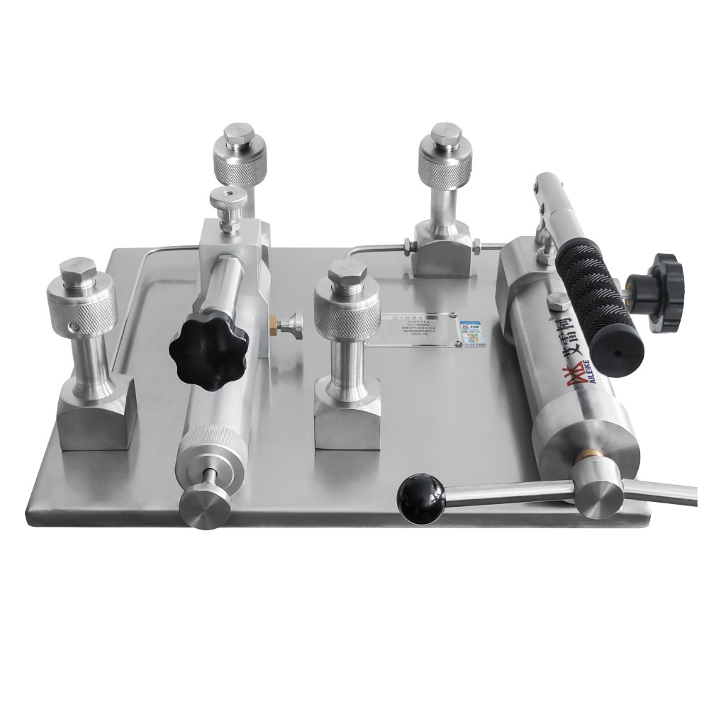
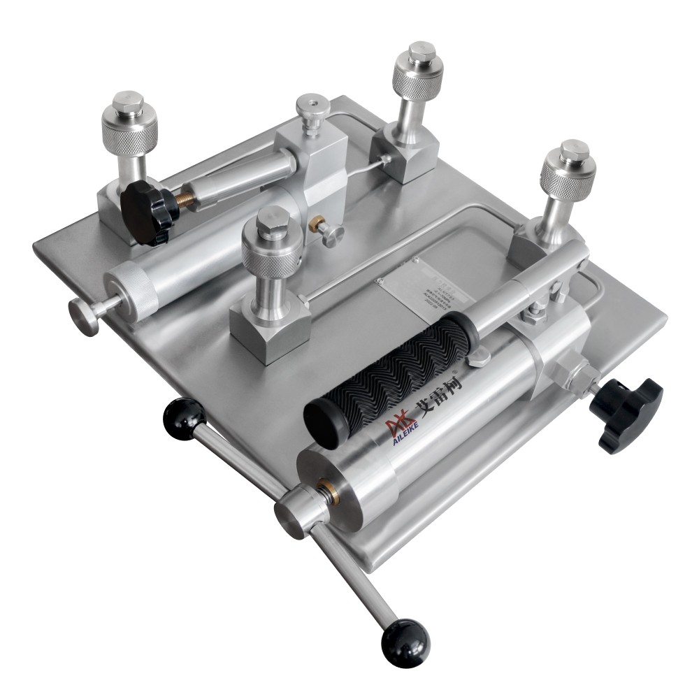
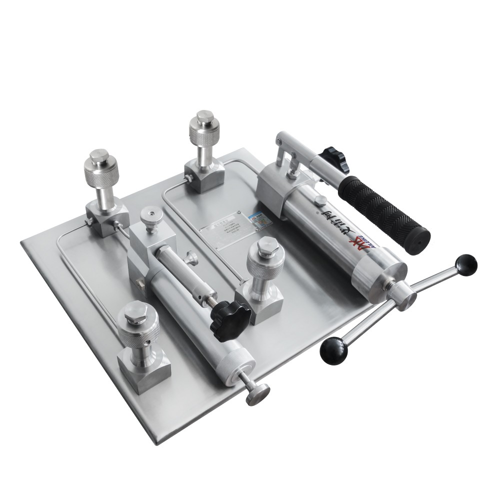
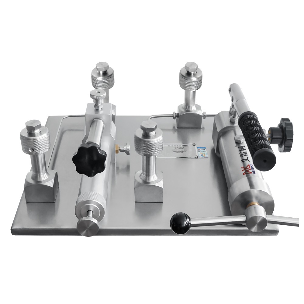
Description
|
01 |
02 |
|
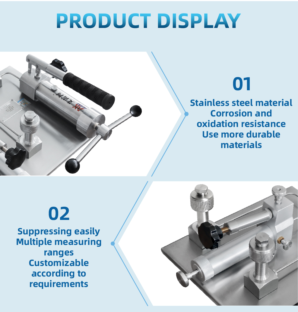
Stainless steel material Corrosion and oxidation resistance Use more durable materials
|
Suppressing easily Multiple measuring ranges Customizable according to requirements |
|
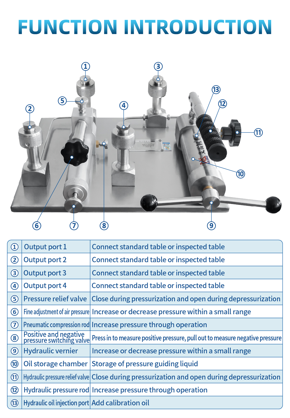
① |
Output port 1 |
Connect standard table or inspected table |
|
② |
Output port 2 |
Connect standard table or inspected table |
|
③ |
Output port 3 |
Connect standard table or inspected table |
|
④ |
Output port 4 |
Connect standard table or inspected table |
|
⑤ |
Pressure relief valve |
Close during pressurization and open during depressurization |
|
⑥ |
Fine adjustment of air pressure |
Increase or decrease pressure within a small range |
|
⑦ |
Pneumatic compression rod |
Increase pressure through operation |
|
⑧ |
Positive and negative pressure switching valve |
Press in to measure positive pressure, pull out to measure negative pressure |
|
⑨ |
Hydraulic vernier |
Increase or decrease pressure within a small range |
|
⑩ |
Oil storage chamber |
Storage of pressure guiding liquid |
|
⑪ |
Hydraulic pressure relief valve |
Close during pressurization and open during depressurization |
|
⑫ |
Hydraulic pressure rod |
Increase pressure through operation |
|
⑬ |
Hydraulic oil injection port |
Add calibration oil |
|
Product name |
Gas liquid dual-use pressure calibration table |
|
Model |
ALKT783 |
|
Pressure range |
-0.95~1000bar/-13~14500psi/-0.095~100MPa(Pressure selectable) |
|
Measurement medium |
Air/Transformer oil 25# |
|
Way of pressure |
Hand movement |
|
Ambient temperature |
0~50℃ |
|
Output port |
Four |
|
Pressure connection |
The default thread size for the pressure output port is M20 × 1.5(F). If you need other thread sizes, please contact us for consultation. |
|
Cover form |
Air pressure min 10Pa/hydraulic pressure min 0.01bar |
|
Product size |
400×455×145mm |
|
Net Weight |
Approximately 14kg |
|
Product size |
600×550×300mm(packaging material is cardboard box) |
|
Packaged weight |
Approximately 29kg |
|
Product packaging size |
Certificate of conformity x 1 Instruction manual x 1 Warranty card x 1 Sealing ring x 4 4 plugs |
|
Working principle and usage |
|
Hydraulic pressure |
|
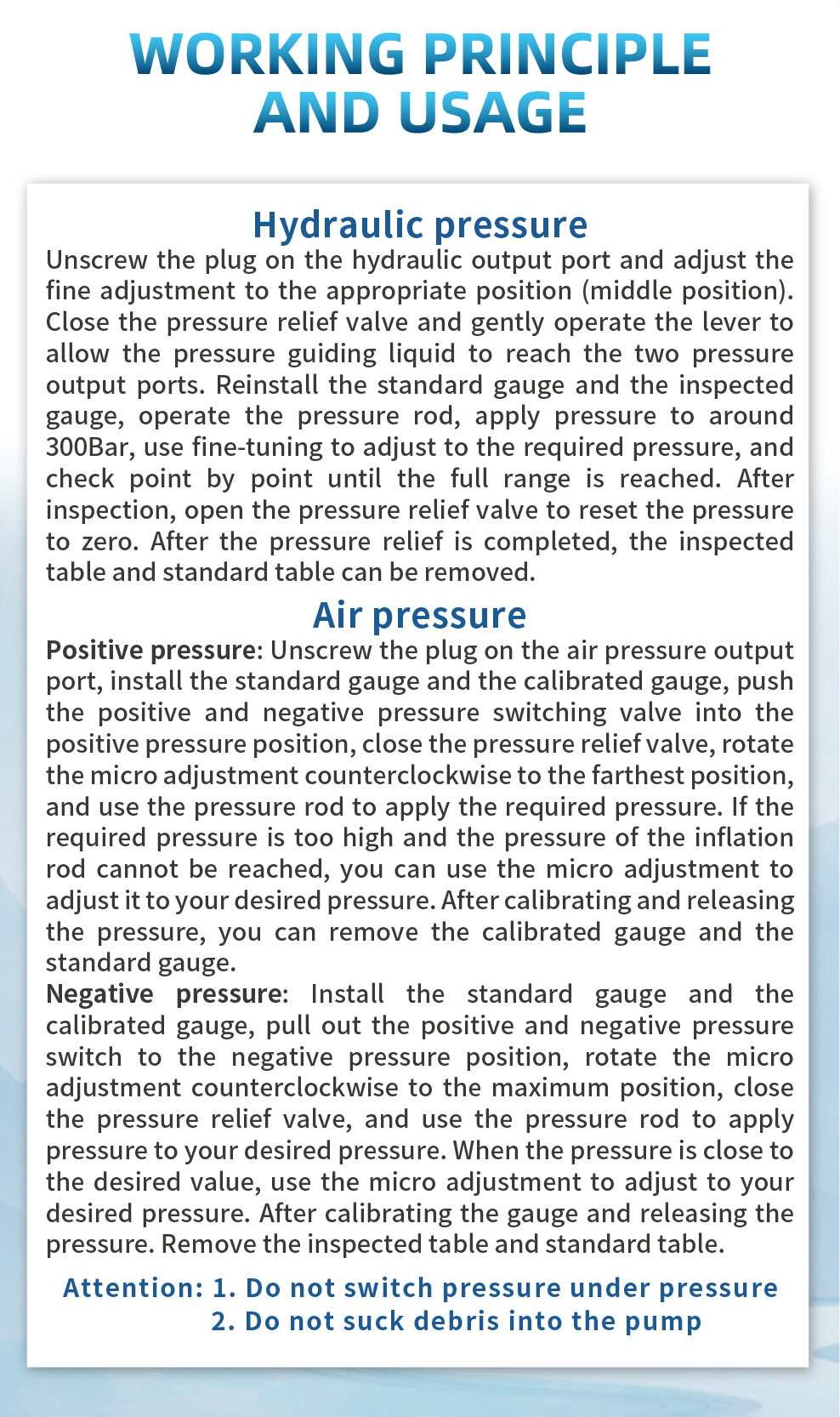
Unscrew the plug on the hydraulic output port and adjust the fine adjustment to the appropriate position (middle position). Close the pressure relief valve and gently operate the lever to allow the pressure guiding liquid to reach the two pressure output ports. Reinstall the standard gauge and the inspected gauge, operate the pressure rod, apply pressure to around 300Bar, use fine-tuning to adjust to the required pressure, and check point by point until the full range is reached. After inspection, open the pressure relief valve to reset the pressure to zero. After the pressure relief is completed, the inspected table and standard table can be removed. |
|
Air pressure |
|
Positive pressure: Unscrew the plug on the air pressure output port, install the standard gauge and the calibrated gauge, push the positive and negative pressure switching valve into the positive pressure position, close the pressure relief valve, rotate the micro adjustment counterclockwise to the farthest position, and use the pressure rod to apply the required pressure. If the required pressure is too high and the pressure of the inflation rod cannot be reached, you can use the micro adjustment to adjust it to your desired pressure. After calibrating and releasing the pressure, you can remove the calibrated gauge and the standard gauge. Negative pressure: Install the standard gauge and the calibrated gauge, pull out the positive and negative pressure switch to the negative pressure position, rotate the micro adjustment counterclockwise to the maximum position, close the pressure relief valve, and use the pressure rod to apply pressure to your desired pressure. When the pressure is close to the desired value, use the micro adjustment to adjust to your desired pressure. After calibrating the gauge and releasing the pressure. Remove the inspected table and standard table. |
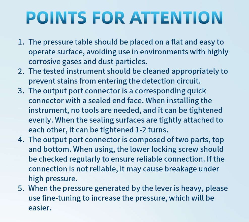
Points for attention
1、The pressure table should be placed on a flat and easy to operate surface, avoiding use in environments with highly corrosive gases and dust particles.
2、The tested instrument should be cleaned appropriately to prevent stains from entering the detection circuit.
3、The output port connector is a corresponding quick connector with a sealed end face. When installing the instrument, no tools are needed, and it can be tightened evenly. When the sealing surfaces are tightly attached to each other, it can be tightened 1-2 turns.
4、The output port connector is composed of two parts, top and bottom. When using, the lower locking screw should be checked regularly to ensure reliable connection. If the connection is not reliable, it may cause breakage under high pressure.
5、When the pressure generated by the lever is heavy, please use fine-tuning to increase the pressure, which will be easier.


 English
 Portuguese
  Indonesian
  Russian
  Arabic